Guides / Process
3+2 Machining: How a Shop Sets Up a Tilted Work Plane
October 10, 2026
Most 5-axis prototypes are not cut with all five axes moving at once. They are cut in 3+2 mode: the machine tilts and rotates the part, locks both rotary axes, and then runs a normal three-axis program. The result is one clamping, short tools and holes drilled square to angled faces, without the programming and prove-out effort that simultaneous motion needs.
This guide explains how a shop sets up a tilted work plane, what the setup costs you and where 3+2 stops being enough. For the wider comparison, see simultaneous vs 3+2 for prototypes. This post is one part of our guide to 5-axis CNC prototyping.
What the “3+2” actually means
The three is X, Y and Z, the linear axes. The two is the pair of rotary axes: on a trunnion machine usually A (tilt) and C (rotation), on a swivel-head machine B and C or A and C. In 3+2 mode the program does three things in order:
- Rotate and tilt to a defined angle.
- Lock the rotary axes (some controls hold them with position loops, others clamp them).
- Cut the features on that plane with ordinary X, Y and Z moves.
Then it indexes to the next angle and repeats. Because the rotary axes do not move during the cut, the stiffness of the setup is close to a 3-axis machine and the toolpaths are easy to read and verify.
How a tilted work plane is defined
Every orientation needs its own coordinate system. In CAM the programmer creates a work plane for each group of features: its origin, its Z direction (the tool axis for that plane) and its X direction. The post-processor then turns that into machine code.
On the control side, the instruction has different names depending on the brand. Fanuc-style controls use tilted work plane commands such as G68.2. Heidenhain controls use the PLANE functions. Siemens controls use a swivel cycle called CYCLE800. You do not need to know these for an RFQ, but it helps to know that a competent shop has the feature on its machine and has used it. The key property is that the control keeps track of the tilt, so a program written in the tilted plane’s coordinates lands where the CAM simulation said it would.
Two things set the quality of the result:
- The pivot reference. The machine needs to know where the rotary axes pivot relative to the table and the spindle. Shops calibrate this with a probe and a reference sphere or a similar artifact. A drift here shows up as a step where two orientations meet.
- The work offset on the part. Shops pick one datum on the part or fixture and let the control carry it through every tilt. Setting a separate offset by hand for each orientation adds error.
Where 3+2 saves setups
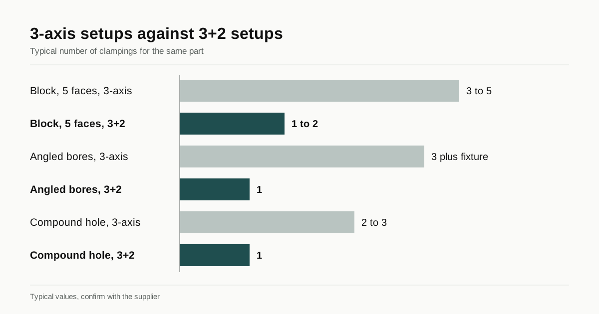
A prismatic part with features on five faces is the classic case. A 3-axis machine needs a new clamping for each face. A 3+2 machine reaches the top and four sides in one clamping, as long as the fixture leaves them exposed. The table below is typical orientation, not a promise.
| Part type | Typical 3-axis setups | Typical 3+2 setups | Why |
|---|---|---|---|
| Block with features on 5 faces | 3 to 5 | 1 to 2 | All faces reachable by tilting |
| Housing with angled bores | 3 plus a special fixture | 1 | Bores drilled along their own axis |
| Bracket with a compound-angle hole | 2 to 3, often with a sine plate | 1 | Plane defined at the hole angle |
| Flat plate with simple pockets | 1 to 2 | 1 to 2 | No benefit, use the cheaper machine |
Fewer setups mean fewer chances to introduce error between faces and less labor on the first part. On a one-piece prototype, that is often the difference between a part that matches the model and one that needs rework.
Shorter tools, better surface
Tilting the part toward the tool lets the shop use a shorter tool and hold. A long, thin end mill reaching into a deep pocket on a 3-axis machine will chatter and deflect. If the part is tilted so the pocket opens toward the spindle at a better angle, a shorter tool does the same work with a cleaner wall. This is one of the quiet reasons 3+2 parts often show better finishes on angled faces than the same faces cut with a 3-axis setup and a sine plate.
Holes benefit the most. A drill that meets an angled face at 90 degrees starts cleanly, stays straight and breaks through square. A drill that meets an angled face at 60 degrees tends to walk and leaves an oval entry.
What limits 3+2
3+2 is not free of trouble. Shops plan around these points:
- Collision. When the part tilts, the tool holder, spindle nose or fixture can swing into something. CAM simulation with the real machine model catches most of it. A prototype with a first-time program is where a collision is most likely, so the first cuts are often run slowly or in air.
- Travel limits. Tilt and rotation ranges differ by machine. A part that is tall or wide may leave too little room once it tilts, and the shop has to pick a different machine.
- Tool reach. Deep, narrow features at an angle need long tools. At some depth the tool is the limit, and you may need to change the design.
- Surfaces that never stop curving. A blended blade or sculpted face cannot be cut well in fixed orientations. You get visible facets or a lot of hand work.
3+2 or simultaneous: a quick test
Ask these questions about your part:
| Question | If yes |
|---|---|
| Are all angled features flat faces, holes or pockets? | 3+2 is enough |
| Does one surface continue smoothly across two or more tilt angles? | Simultaneous is likely needed |
| Is the tool reach into the feature short compared with its diameter? | 3+2 is usually fine |
| Do blades, a blend or an impeller form part of the geometry? | Simultaneous |
| Is it a one-piece form and fit test with soft tolerances? | 3+2 is the lower cost choice |
If you cannot tell, say so in the RFQ. A shop that has seen similar parts will tell you which one it plans to use and why, and that tells you something about its experience too.
What to put in your RFQ
You do not need to specify 3+2. Describing the part clearly is enough, and you should leave the process choice to the shop unless you have a reason. These items help:
- A STEP file, so the shop can find the angled features and check collision in its own CAM.
- A drawing with the angled features dimensioned from a clear datum, not from each other.
- The tolerance on any feature that spans two orientations, such as a bore that exits on an angled face.
- Which faces are cosmetic or sealing, so they are cut with the best surface strategy.
Designing parts for 5-axis machining covers corner radii, tool reach and datum choices in more detail.
Checklist before you send the part
- Mark the features that sit at an angle and give each its angle to a named datum.
- Check that holes on angled faces have enough material around them at the exit.
- Keep pocket depth within a few tool diameters wherever you can.
- State tolerances only where the function needs them, and say which feature spans two orientations.
- Decide whether the part will be one piece or a short run, since 3+2 programs carry over well to repeat orders.
When the drawing is ready, send it through the RFQ form. We match it with up to three shops that run 5-axis for prototypes. They quote you directly, matching is free for buyers and you get a reply within 24 business hours.
Frequently asked questions
Is 3+2 machining the same as 5-axis machining?
It runs on a 5-axis machine, but the two rotary axes only position the part and then lock. All cutting happens in three linear axes. Simultaneous 5-axis moves all five axes while the tool is cutting.
Does 3+2 give the same accuracy as a 3-axis mill?
Within a single orientation the cutting behaves like a 3-axis mill. Accuracy between orientations depends on how well the machine's rotary axes are calibrated and how the shop sets the work offset. Ask for a measured result on features that span two orientations.
When does a part need simultaneous motion instead of 3+2?
When the surface itself is continuous and changes angle, such as a blade, a blended port or a sculpted housing. Flat faces, holes and pockets at fixed angles are 3+2 work.
Need this prototype quoted?
Send the drawing. We match you with up to 3 5-axis shops and reply within 24 business hours.
Get matched with a 5-axis shop